
Azimuth / Headline Errors informs us the Radar Processor can not detect Antenna Rotation.
- The Radar system may show additional errors such as Trigger or Video. In most cases, resolving the Headline / Azimuth errors will clear all other alarms.
- If the Radar System shows RF error at any point, please contact your nearest Service Provider for additional support.
Basic Fault Finding Steps for Azimuth / Headline errors as Follows :
Go outside and visually check Antenna is Rotating.
-
No : Antenna is not Rotating
-
Yes : Antenna is Rotating, Display shows Azimuth Error
-
Yes : Antenna is Rotating, Display shows Headline Error
-
Yes : Antenna is Rotating, Display shows both Headline & Azimuths Errors
- Add Button
- Reed Switch
- 03P9347 BP GEN PCB (either A or C version depending on placement of Opto Coupler. Take photo of existing PCB to assist with ordering new part)
- 03P9347 RF TB PCB
- Suspect either the Antenna Motor or Carbon Brushes.
- Crew can check condition of Carbon Brushes by Downloading and following this Guide : FAR-2xx7 Carbon Brush Check.pdf
- Please remember to power down Radar system, isolate from power and make safe, prior to opening the Antenna Gearbox.
If Antenna is S-Band Model :
- Suspect either 3 phase motor supply, PSU-007 (Thermal Relay) fault, MSS PCB Fault, Motor failure and/or issue with the Drive/Driven Gears.
In most cases, issues with S-Band Radar will require Service Engineer attendance. Following items will need to be checked :
- Check 3 phase motor supply going into PSU-007
- Check Thermal Relay inside PSU-007 has not Tripped. Please reset and test.
- Check MSS PCB inside S-Band Antenna. You can carry out MSS Bypass procedure as temporary test/fix : SBAND MSS-7497 bypass procedure.pdf
- Check Drive / Driven Gear are in good condition and not over worn
- Test Condition of S-Band Motor.
S-Band Antenna Motor uses 3 phase power supply. Extreme Caution should be taken when working / testing equipment using high voltage.
If safe to do so, please power the Radar system down, isolate from power and make safe.
Open the Antenna and locate the Azimuth Disk.
Clean the Azimuth Disk with a Cloth and Brush.
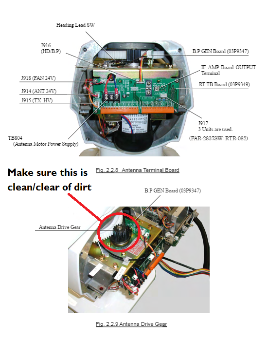
Once Azimuth Disk is clean and free of dirt/debris, please close Antenna Gearbox, power system on and test.
If issues still persist, the following parts are most common cause :
- 03P9347 BP GEN PCB (either A or C version depending on placement of Opto Coupler. Take photo of existing PCB to assist with ordering new part)
- 03P9347 RF TB PCB
- If RF Error is shown, please contact your nearest Service Provider for additional support.
Please run Self Test
- Press MENU > 9 [Customise/Test] > 8 [Tests] > 2 [Self Test]
- If RFC values show *****, please contact your nearest Service Provider for additional support.
- If all Self Test values are shown correctly, please carry out the following :
First check Azimuth Error :
If safe to do so, please power the Radar system down, isolate from power and make safe.
Open the Antenna and locate the Azimuth Disk.
Clean the Azimuth Disk with a Cloth and Brush.
Once Azimuth Disk is clean and free of dirt/debris, please close Antenna Gearbox, power system on and test.
If issues still persist, the following parts are most common cause :
- 03P9347 BP GEN PCB (either A or C version depending on placement of Opto Coupler. Take photo of existing PCB to assist with ordering new part)
- 03P9347 RF TB PCB
- Reed Switch